When trying to program the ESP8266 with an USB-TTL interface without any additional circuitry, one has to connect GPIO0 to ground before powering on or hitting RESET in order to put the ESP8266 into the flashing mode. In order to automate this procedure several circuits are proposed, the most common and bullet proof one being the one from the NodeMCU people: https://github.com/nodemcu/nodemcu-devkit. This circuit uses the DTR (“Data Terminal Read”) and RTS (“Request To Send”) lines from the USB-RS232-TTL interface chip (CP2012 or CH340 depending on the revision of the ModeMCU).
There is another possibility to connect DTR and RTS without using transistors, e.g.: https://bykting.wordpress.com/2015/08/18/flashing-esp-modules-with-arduino-ide/. This might however lead to problems when using the serial monitor.
When using an USB-RS232-TTL interface without RTS output one has to use a different approach,as described in: https://hallard.me/esp8266-autoreset/.
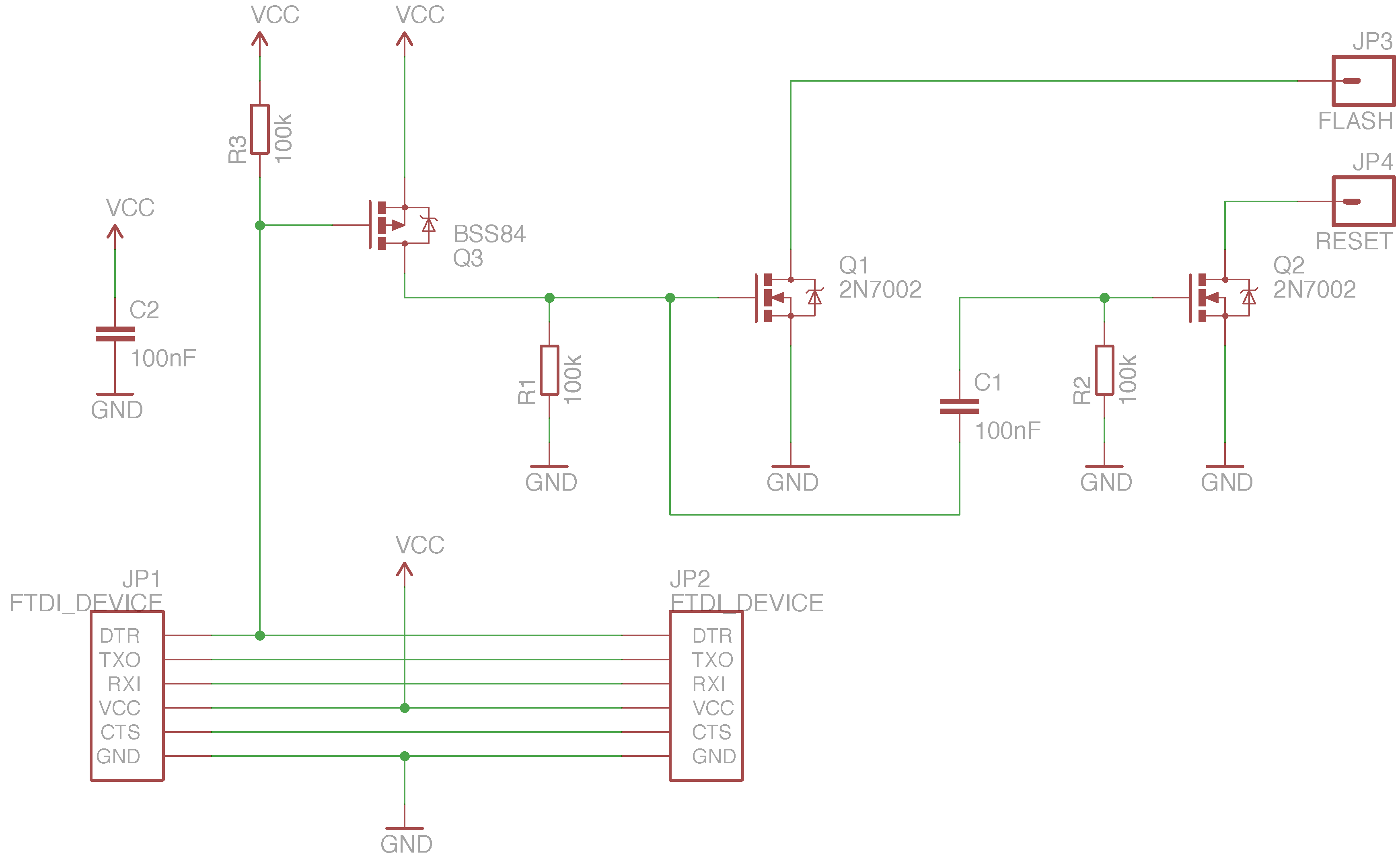
Unfortunately this does not work for all circuits, especially when the ESP8266-Module is already wired to other components. Hence the RC-compenent was decoupled by using transistors, which finally led to this schema:
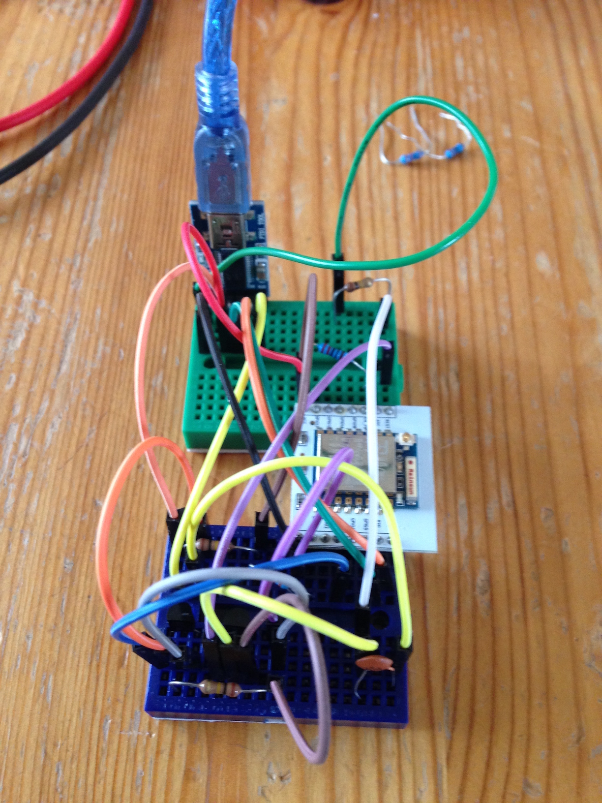
The prototype worked well in all tested use cases:
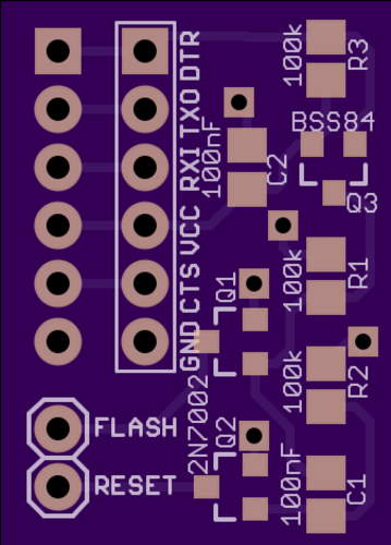
A PCB version of this design can be ordered via OSH Park. The board has been tested and works like expected.