ESP pogo-pin programmer with autoreset

Featured

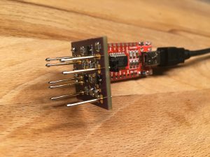
A new version of the aforementioned adapter board has been developed which can be used to program the standard ESP8266 board like the ESP-07, ESP-12E, ESP-12F via pogo pins. This new adapter board just requires a standard FTDI programmer and generates the required reset and flash signals.

A PCB of the adapter board can be ordered via OSH Park. The board has been tested and works like expected.


Autoreset and flashing circuit for ESP8266 with FTDI interface

Featured

When trying to program the ESP8266 with an USB-TTL interface without any additional circuitry, one has to connect GPIO0 to ground before powering on or hitting RESET in order to put the ESP8266 into the flashing mode. In order to automate this procedure several circuits are proposed, the most common and bullet proof one being the one from the NodeMCU people: https://github.com/nodemcu/nodemcu-devkit. This circuit uses the DTR (“Data Terminal Read”) and RTS (“Request To Send”) lines from the USB-RS232-TTL interface chip (CP2012 or CH340 depending on the revision of the ModeMCU).

There is another possibility to connect DTR and RTS without using transistors, e.g.: https://bykting.wordpress.com/2015/08/18/flashing-esp-modules-with-arduino-ide/. This might however lead to problems when using the serial monitor.

When using an USB-RS232-TTL interface without RTS output one has to use a different approach,as described in: https://hallard.me/esp8266-autoreset/.

Unfortunately this does not work for all circuits, especially when the ESP8266-Module is already wired to other components. Hence the RC-compenent was decoupled by using transistors, which finally led to this schema:
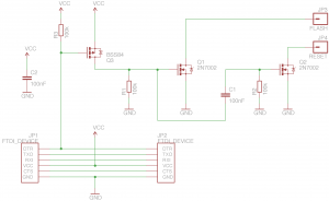
The prototype worked well in all tested use cases:
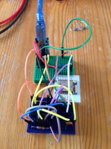
autoreset_test_breadboard_small

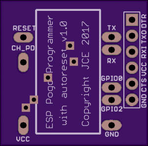
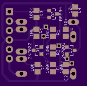
A PCB version of this design can be ordered via OSH Park. The board has been tested and works like expected.
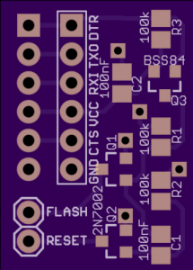
autoreset_brd_top


How to repair a servo driver on a WLToys V922 or WLToys V944

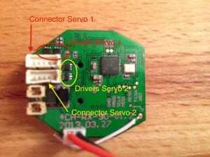
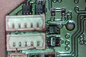
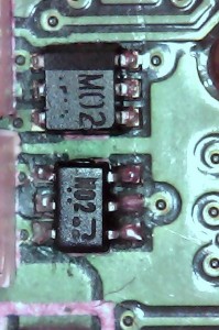
On my the V944 one of the servos stopped working. After investigation the culprit was identified as the FET driver chip on the main board. The defunct chip showed a slight deformation from the heat and had a brownish shimmer. The chip was labeled M02 and was found to be the double MOSFET (N-channel and P-channel) US6M2 from ROHM. The datasheet of the US6M2 can be found here

The original chip has the size of 2mm x 1.7mm. A replacement ordered on AliExpress showed a slightly different dimension of 2mm x 1.25mm (SOT 363 package) but  the helicopter was fully functional after the replacement.

The soldering was a little bit tricky as the servo connector had to be removed in order to reach the defect chip.

Here are some pictures:

V944 Board
V944 Board Closeup
V944 Board Closeup 2

The same FET driver chips are used for the V922 helicopter and probably for other WLToy models. Unlike the V944, the drivers of the servos of the V922 helicopter are not located on the main board but on each of the servo boards.